VMware NSX Layer 2 Bridge Configuration
I have been playing around a lot with NSX in the home lab lately and decided to revisit the NSX Layer 2 Bridge functionality especially since now much of the configuration can be done in the HTML 5 interface. The NSX Layer 2 Bridge is an interesting tool that can be used in various use cases that can be helpful. There can be requirements from a network perspective that require ensuring the same layer 2/broadcast domain for workloads to be able to communicate from a network perspective. In this post, we will take a look at VMware NSX Layer 2 Bridge Configuration and the various use cases and capabilities as well as limitations.
What is the purpose for the Layer 2 Bridge?
The Layer 2 bridge makes communication from a logical switch and a physical VLAN possible by bridging the Logical Switch to the physical network by way of a VLAN enabled Distributed Port Group. What are the use cases for this type of configuration?
The following use cases are defined by VMware as potential Layer 2 bridge use case candidates:
Physical to virtual, or virtual to virtual migration – Using the NSX layer 2 bridge you can migrate workloads inside NSX and outside without losing the IP addressing scheme needed for communication
- Allow physical resources to be able to communicate with the VMs that reside on a logical switch.
- The Layer 2 bridge also allows integrating a physical network device such as a router into the NSX environment.
Additional use cases that are found in many real world environments include the following:
- DR use cases where reconfiguring IP addresses is not a consideration due to constraints in legacy applications
- Hybrid cloud environments where again, you need to have the same IP addresses configuring and connectivity between the cloud and on-premises environments on the same layer 2 broadcast domain.
VMware NSX Layer 2 Bridge Configuration
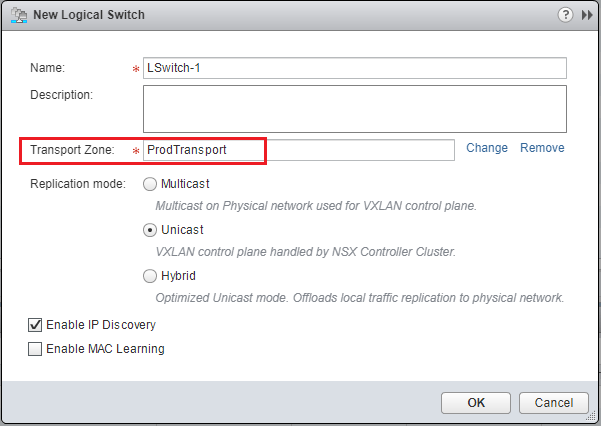
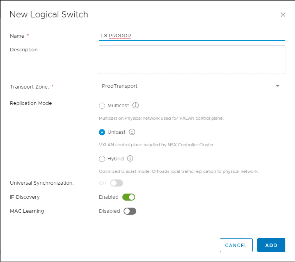
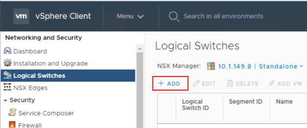
The first thing I am going to do is create a NSX Logical Switch. The Logical Switch is the VXLAN based switch that can create logical networks across physical network infrastructure. This means you can have the same address space across different underlying routed networks. Navigate to NSX Local Switches > Add.
The New Logical Switch dialog box has you name the Logical Switch, Transport Zone, Replication Mode, and the type of discovery.

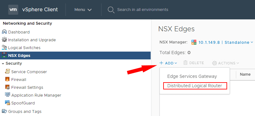
Once the Logical Switch is created, we can now create the Distributed Logical Router. Navigate to NSX Edges > Add.
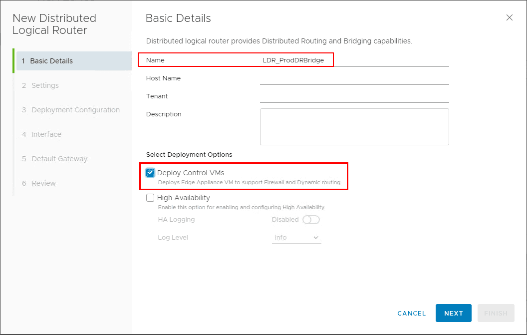
The New Distributed Logical Router wizard launches. The first screen has you configure the basic details of the DLR. Under the deployment options, you can deploy the Control VMs and High Availability if desired.
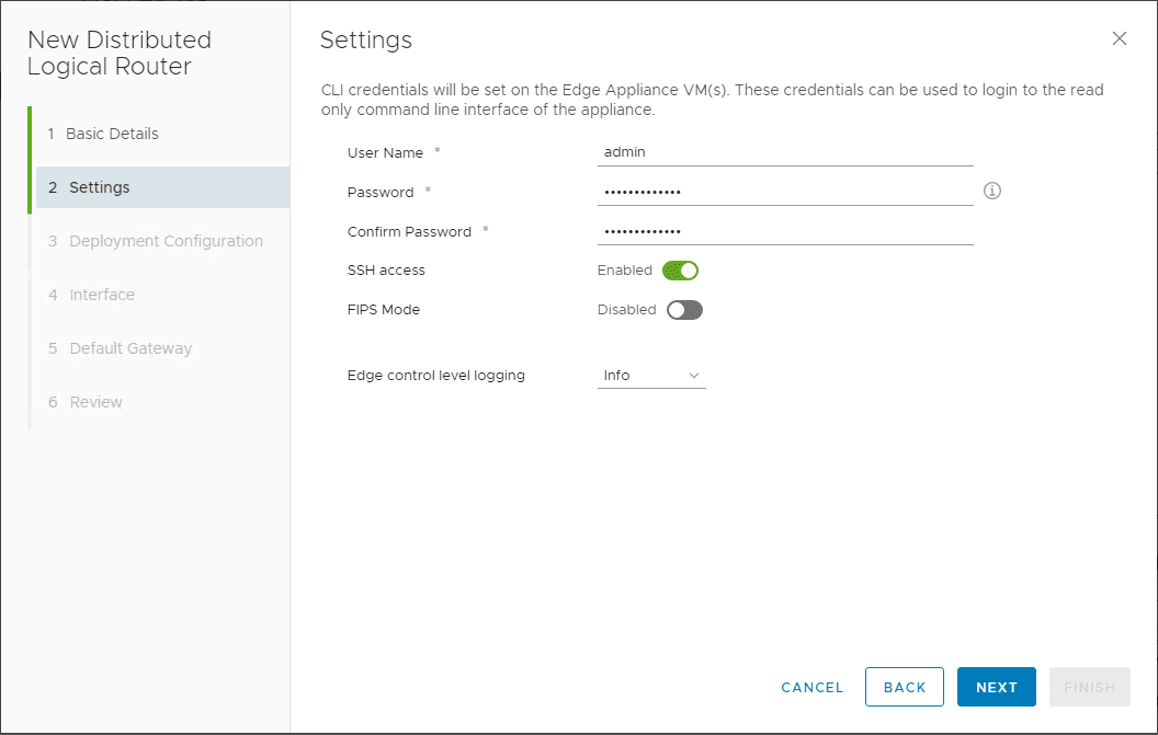
Configure the user name and password as well as SSH configuration and FIPS mode.
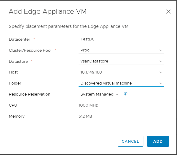
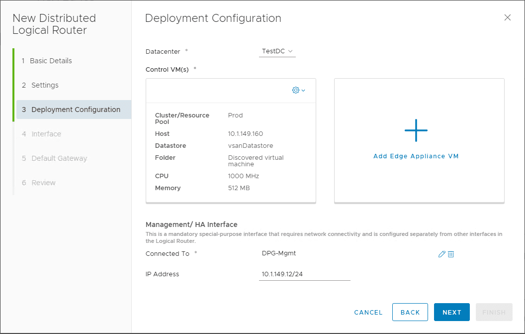
On step 3, the deployment configuration, click the big plus sign for Add Edge Appliance VM.
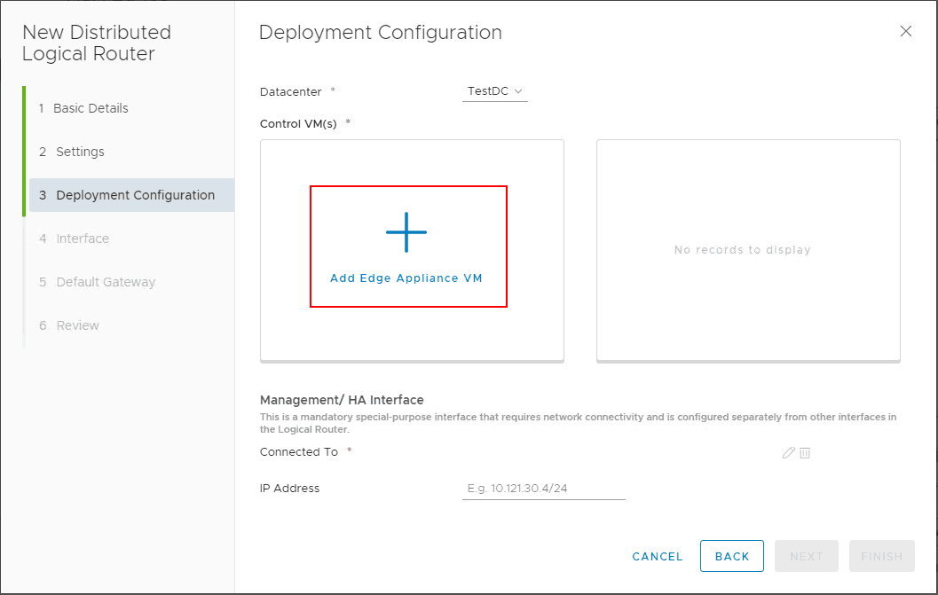
The Add Edge Appliance VM dialog box pops up. The VM configuration includes the Datacenter, Cluster/Resource Pool, Datastore, Host, Folder, Resource Reservation, CPU, and Memory.
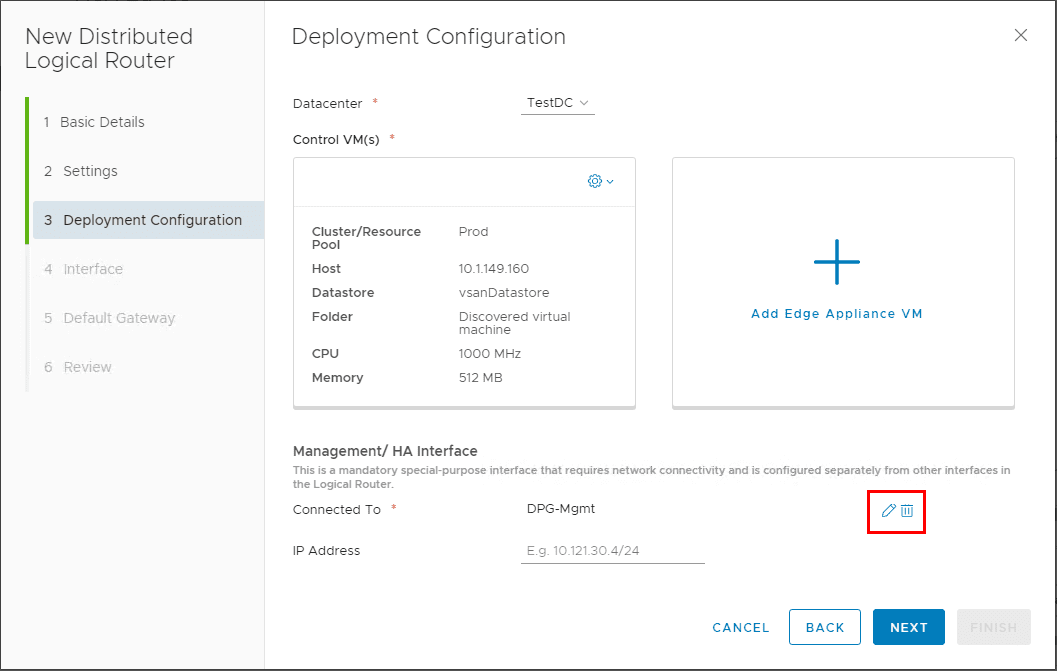
Click the edit pen under the Management/ HA Interface configuration.
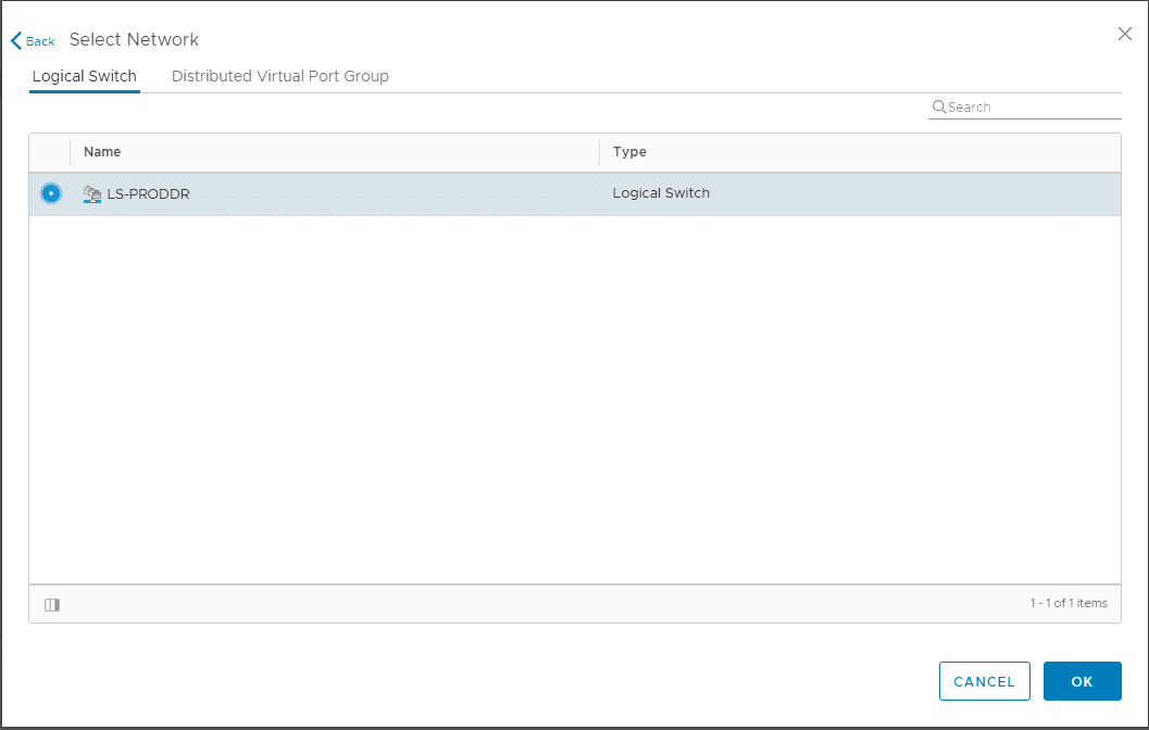
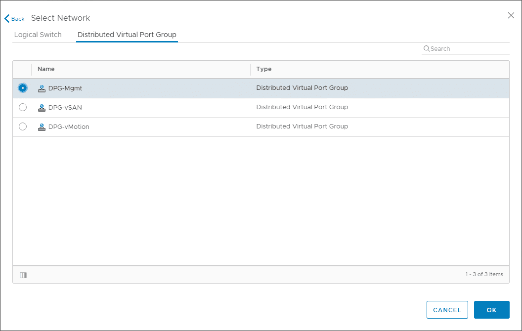
You can select the management interface to reside on the Logical Switch or the Distributed Virtual Port Group.
Deployment configuration is set including the Management/HA Interface.
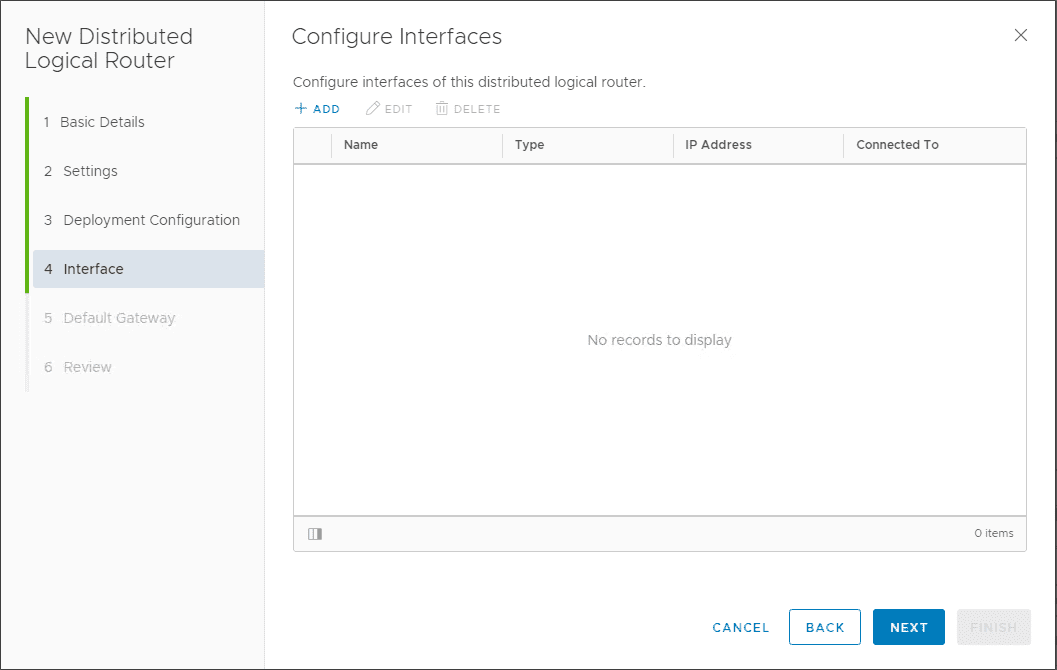
On the configure interfaces, you can leave this blank here.
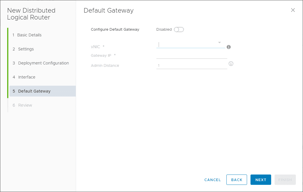
Default Gateway can be left blank.
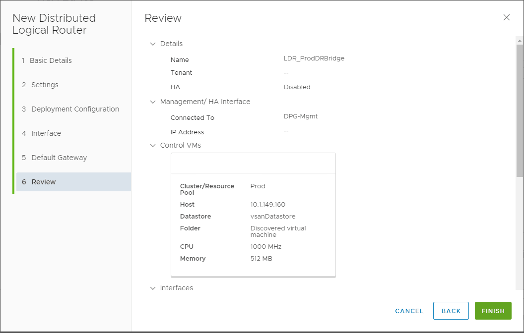
Review and confirm the Distributed Logical Router configuration.
The DLR is deployed successfully.
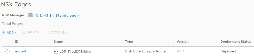
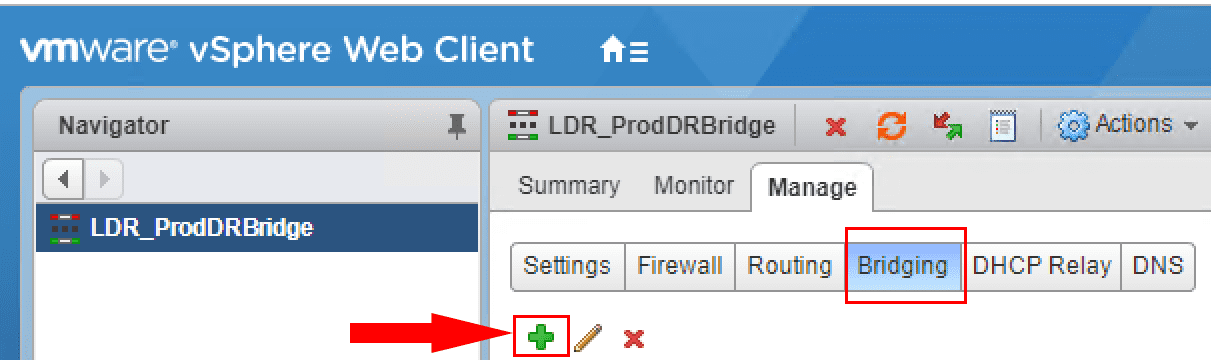
To deploy the Layer 2 Bridge, we need to go back to the Flex client and Manage the properties of the Distributed Logical Router. Click Bridging and then click the green plus sign.
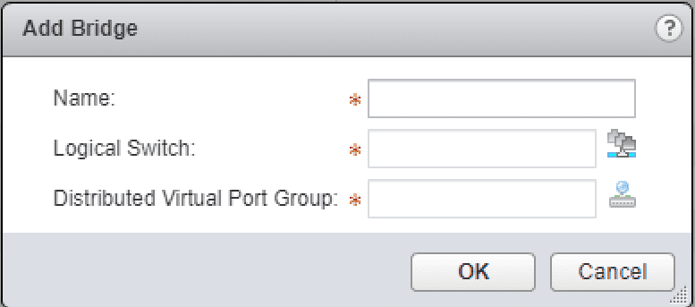
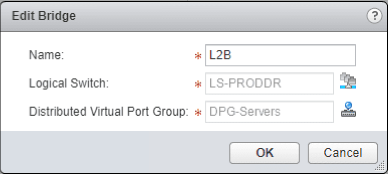
The Add Bridge configuration pops up. You have to assign a name, Logical Switch, and Distributed Virtual Port Group. ***Note*** There are a couple of very important details on the Distributed Virtual Port Group that can be used.
- You must have a VLAN ID assigned to the DPG, default VLAN 1 won’t work.
- The Distributed Port Group must be a port group on the same vSphere Distributed Switch that handles the VXLAN VTEPs
- If either of the two things above are not true, you will not see the expected DPG appear on the selection screen.
- The Layer 2 Bridge is also pinned to the particular host that is providing the bridge from Logical to physical.
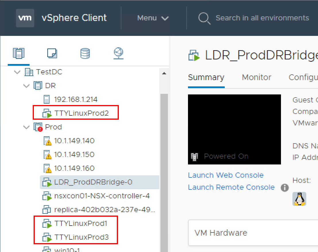
As you can see below, the test workstations are in different routed environments or at least TTYLinuxProd 2 when compared to TTYLinuxProd1. TTYLinuxProd3 is on the physical DGP backed VLAN and not on the Logical Switch.
Pings between the two workstations on the Logical Switch are successful. This shows that VXLAN traffic is successful.
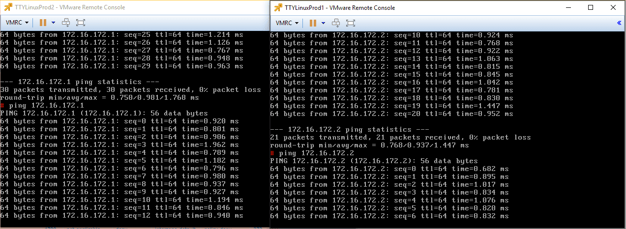
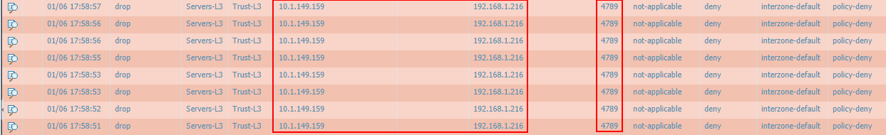
Just a note here. Before the successful ping tests above between the two workstations connected on the Logical Switch, my Palo Alto firewall was blocking the VXLAN UDP traffic between the VTEPs. I had to add an exception for this traffic. Keep in mind this is a consideration for successful VXLAN communication between VTEPs that span routed environments where a firewall(s) is in play.
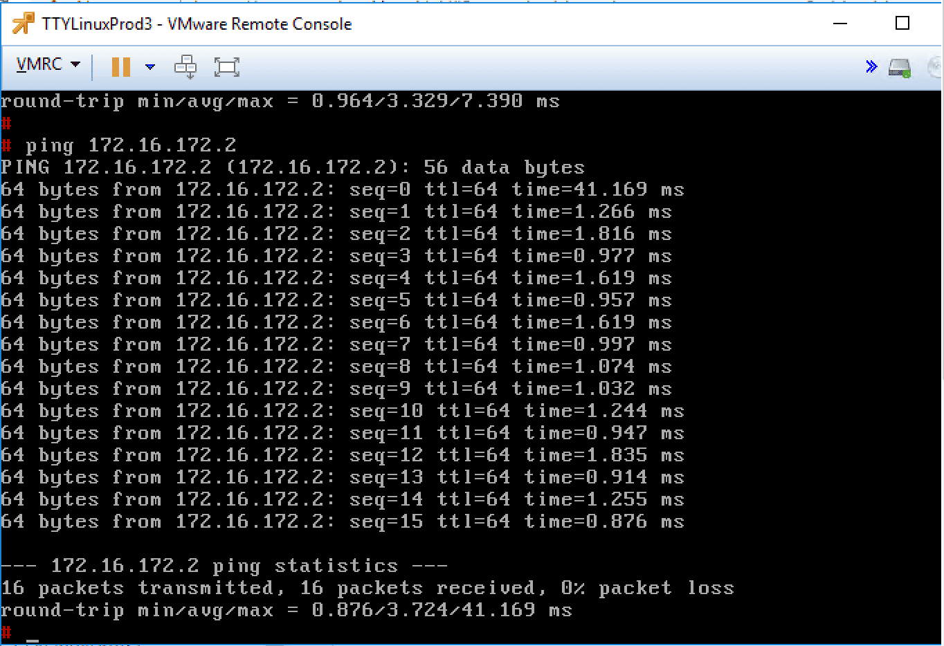
After attaching the layer 2 bridge in the environment, I can now successfully ping from TTYLinuxProd3 workstation on the VLAN backed DPG. We have successfully bridged traffic between the Logical Switch and the “Physical” network backed by a VLAN.
Takeaways
VMware NSX Layer 2 Bridge Configuration provides an extremely interesting and powerful tool to be able to extend these VXLAN enabled networks to the physical network or a “physical” network that is comprised of a virtual portgroup that is backed by a VLAN. The Layer 2 bridge can be a great way to alleviate network constraints in legacy applications that may need to have the same IP scheme and layer 2 broadcast domain. Using NSX, the possibilities to have your networks live “anywhere” becomes much more doable without having too much network complexity. Keep in mind the constraints with the L2 Bridge including the requirement for a VLAN backed DPG, the DPG must exist on the same vDS that hosts the VTEPs.