Ubiquiti NanoBeam 5AC Gen2 Bridge VLAN Configuration
As I have written about recently, I have been working with a pair of Ubiquiti NanoBeam 5AC Gen2 bridge devices to connect my house with a shop for PTP connectivity from my main home data center out to what I am using for my DR location for the home lab. So far, the units are working great and doing exactly what I need them to do. I wanted to write up a quick little article on the VLAN configuration on the devices and how I have mine configured in case this helps others to configure theirs out of the box. Let’s take a look at Ubiquiti NanoBeam 5AC Gen2 Bridge VLAN configuration to see how you get a general VLAN configuration up and running out-of-the-box.
Ubiquiti NanoBeam 5AC Gen2 Bridge VLAN Configuration
I have to admit, I didn’t do a lot of reading before simply throwing these two units up and playing with them. But, that’s part of the fun right? So, I discovered a few things along the way that led to a couple of resets to factory.
My use case was simple. I had a management VLAN that I wanted to be able to use to connect to the two units on my management network. However, I also had three VLANs or so that I wanted the unit to be able to “trunk” across the wireless bridge point-to-point link.
I assumed there was some special configuration that I needed to put in place to make this happen, however, as it turns out, this wasn’t the case.
Configuration for Trunking All VLANs
To get started, you can either get this initial configuration up and running via the UBNT mobile app or you can connect to the units via a laptop. I went the mobile route for the initial configuration, so what I am showing below is “after the fact” connected via a machine on the network.
As I described in my previous article, the NanoBeam 5AC Gen2 bridge unit has a management radio that becomes active for 15 minutes by default to allow management activities on the units. After that time period (configurable) the management radio turns off.
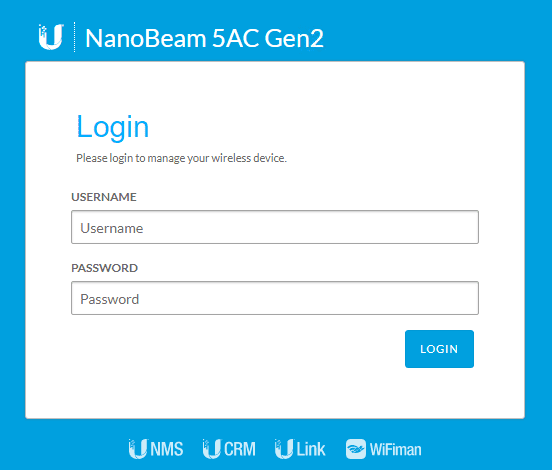
Login to your unit with the default user account/password (if default settings). Default credentials are ubnt/ubnt.
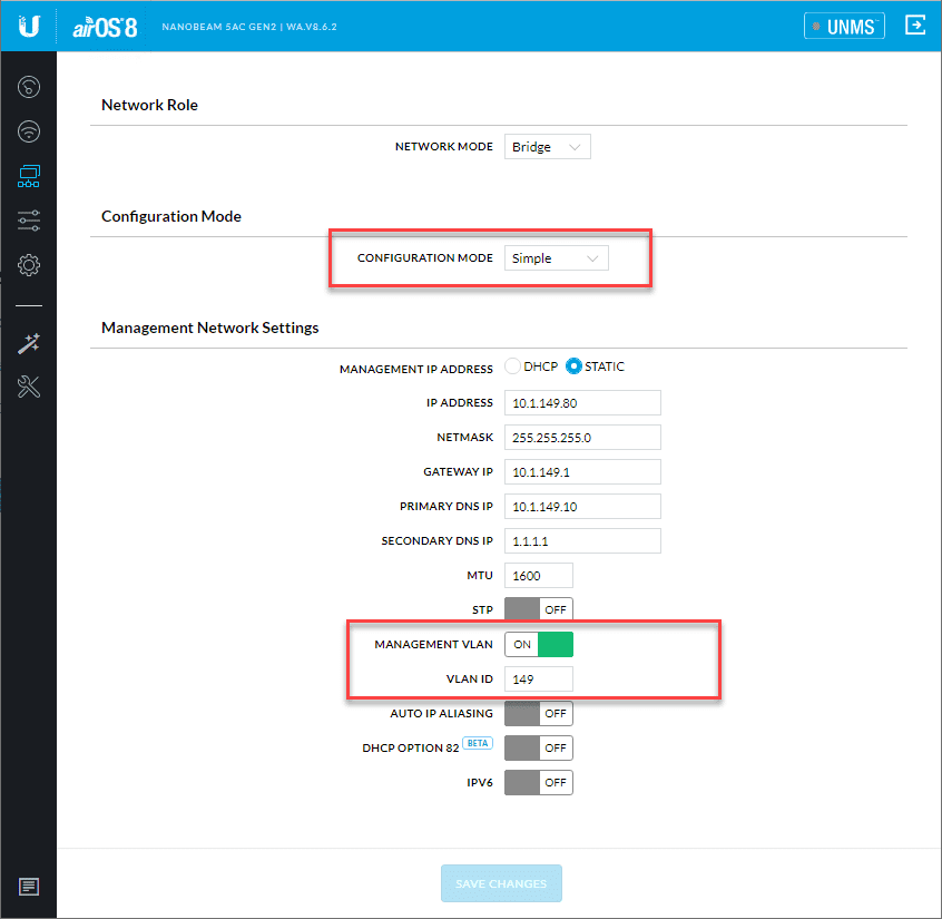
In simple bridge mode, the wireless bridge will forward on all VLAN tags between the link. So, you do not have to define those under advanced configuration mode as I mistakenly assumed.
As you can see below, I have the unit set to Simple configuration mode. Also, I did want to specify the management VLAN. This defines the VLAN for the management network if you want to tag the management traffic with a specific VLAN ID as I did.
Flip the toggle to On and enter your VLAN ID information.
Aside from defining the management VLAN, the bridge units will pass all VLAN IDs between them.
One thing that did cause an issue for me initially which was self-imposed. Make sure your native VLAN configured on one side matches the native VLAN ID on the other side.
Cisco devices will display a “Native VLAN mismatch detected” in the console. I had a mismatch between one side and the other and was not seeing the VLAN ID trunked across initially. The exact message:
14-Jan-2020 13:19:53 :%CDP-W-NATIVE_VLAN_MISMATCH: Native VLAN mismatch detected on interface gi1.
This led me down a rabbit hole of trying different advanced settings and such all to no avail. Then after scrutinizing the switch config on both sides of the bridge, I was able to determine there was a mismatch in my configuration.
After correcting the native VLAN configuration on both sides, I was able to see all VLANs bridged across without any issues. My Ubiquiti AP on the DR side was able to be provisioned correctly and pass along VLAN tagged traffic from the various wireless networks configured.
Wrapping Up
Ubiquiti NanoBeam 5AC Gen2 Bridge VLAN configuration turned out to be easier than I thought it would be, especially after correcting the native VLAN configuration issue that I had between the two locations.
It is nice to see that you do not have to have any kind of special configuration to pass VLAN IDs between two locations. By default, even in simple mode, this is the case.


I’m fighting with the same things and I’m a bit of a VLAN noob. One thing I don’t understand, what should be the native VLAN for the port where the local antenna is connected? Should if me the normal VLAN (1) or should it be the management VLAN (in my case 10)?
Mattias,
Thanks for the comment! So the native or untagged traffic can be anything you want it to be. The main question is, what VLAN do you want clients on the other side of the bridge to be on on as their native VLAN? If the other side has a native VLAN of VLAN 10, you can set the native VLAN on the port where your bridge is connected as VLAN 10 and it will pass untagged traffic on this VLAN. You can set the management VLAN tag on the bridge as you want since it has a VLAN tag area in there. So you can manage the bridge from a different VLAN than the native VLAN if that makes sense. Then the bridges themselves are setup in “trunk” mode which means they pass all tagged traffic by default. So you don’t have to worry about tagging the VLANs on the bridges themselves. But, you do need to be sure and tag the ports where they uplink on each side with the VLANs you want them to be able to carry. Let me know if this makes sense.
Brandon
Thanks for the guide, really useful -I’m trying to figure out how this could work for my use case, below:
VID’s:
100 – Management
101 – Private
102 – Public
103 – Security
The NanoBeam’s will reside on the Management network however I also need to pass this as a tagged VLAN for devices further down the chain such as switches that also need to live on this VLAN.
I have all of my VLAN’s tagged on my main switch, with the exception of the Management VLAN as I am using this as untagged so I can access the device, if I set the Management VLAN on the sender and receiver unit to 100 will I be able to access it still, if i tag VID100?
Pretty confusing but I am sure once it’s done once it will make more sense – wasted a day so far back and forth….
Thanks in advance!
Jack,
Thank you for reaching out! I still have my Nanobeams up and running and haven’t had a moment’s trouble out of them. Pretty cool to see how well they have lasted. So it sounds like your untagged VLAN is for management? If so, you wouldn’t want to tag that on your nanobeam as that would result in “double tagging” and you would lose connectivity. I would suggest most likely not setting your untagged VLAN to management as usually you would have more sensitive traffic on your management VLAN and so everything that you put on that VLAN would be deliberate. Otherwise if you have your untagged traffic on your management VLAN, any device that connects without tagging a VLAN would be on your management network if that makes sense. The nanobeams are set basically as trunk devices. They will pass tags for all VLANs that come through them. One thing to keep in mind though, I have used a couple of the little PoE aggregation boxes from Ubiquit (can’t remember what they are called) and these do not pass tagged traffic. So you have to watch which devices you pass traffic through and make sure they are VLAN-aware. Let me know if this helps. Also, create a forum topic if you need more in depth help as I can better assist there.
Thanks Jack,
Brandon