Configure Inter VLAN Routing with Multiple Switches
The question comes up often when talking about inter vlan routing and how this is done with multiple switches in a production environment. Many examples only show inter vlan routing with a single switch. The concept for multiple switches really is the same as setting up inter vlan routing on a single switch. With multiple switches generally you still set one switch (your core or distribution) switch as the switch operating at layer 3 and then point your clients on a particular VLAN to the switched virtual interface (SVI) of the VLAN on the switch you want to use for routing. This sounds complicated but the SVI is simply the IP address you have assigned to that particular VLAN interface on the layer 3 switch. So your core switch is essentially taking the place of the router for routing between the different VLANs.
Your core router or Internet router will then have a route with every SVI address on your layer 3 switch if the VLAN traffic needs to get out to the Internet. This way the core router knows how to get traffic back to the host on each VLAN.
Why would you want to do routing at the switch level? Aren’t routers the best at doing that? Many might wonder, why do you want to take routing away from the router when that is what it is designed to do. Well, the answer is performance. It is inefficient for LAN routed VLAN traffic to travel all the way to the router to have it then send it back into the LAN to its destination. This is sometimes referred to as “router on a stick”. It is way more efficient for today’s more powerful switches to make this routing decision at line speed inside of the switch itself.
To better show how this is configured, I have setup a lab to show the moving parts at each layer from the top (Core router >> core switch >> access switches).
Overview
The below general lab assumes that we are using VLAN1 as the default/native VLAN. VLAN10 and VLAN20 are the additional VLANs we have created to demonstrate inter vlan routing happening at the switch level.
Core Router:
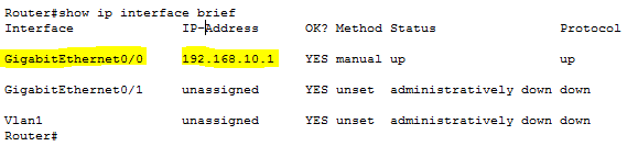
Starting at the core router and working our way down, the core router for simplicity sake has one interface that we have addressed with the IP 192.168.10.1/24 and for the lab serves as the top layer router.
Interface: GigabitEthernet0/0 – IP address 192.168.10.1/24
 Routes:
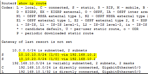
As you can see below we have static routes added for:
- 10.10.10.0/24 via 192.168.10.2
- 10.10.20.0/24 via 192.168.10.2
The address 192.168.10.2 belongs to our core switch where all the inter VLAN magic is going to happen as we will see below.
 Core Layer 3 Switch
On our core layer 3 switch, we have to do a couple of things
- Enable routing – the command to do this will be different between vendors, but most are something along the lines of ip routing at global config mode.
- Create the VLANs and then assign IP/subnet to those VLAN interfaces.
As you can see below the addresses assigned to the VLANs are:
- VLAN1 – 192.168.10.2
- VLAN10 – 10.10.10.1
- VLAN20 – 10.10.20.1
![]()
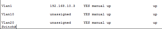
Access Switches
On the Access switches that end user devices are going to connect to, all we really have to do is create the additional VLANs. On our access switches we have assigned an IP address for VLAN1 but this isn’t necessary for inter vlan routing to happen for the clients as the VLAN traffic will simply be handled at layer 2 and the core switch SVI will then take over to route the traffic between VLANs and up the chain. As you can see below we have created the additional VLANs and they don’t have IP addresses assigned to them.
Clients and DHCP
For clients one concern would be getting DHCP addresses. This is taken care of by the ip helper address in the Cisco world, and other vendors generally have similar terminology. The ip helper address is the address of the DHCP server that will answer requests coming from that VLAN.
The DHCP server will typically have multiple scopes configured and the way it knows which address to assign is the gateway address it sees passing the DHCP request from. So if the request comes from the switch SVI for VLAN 20 address 10.10.20.1 the DHCP server will know to hand out an address for the 10.10.20.x subnet. So you can have multiple address pools sitting there answering requests from multiple subnets
The DHCP server also doesn’t have to sit on all the VLANs for this to work, it simply has to have an address the switch can get to and in our case this address sits on the default VLAN1. So our DHCP server is assigned the address 192.168.10.67 and the gateway address of the VLAN1 SVI of the switch which is 192.168.10.2.
Clients will then receive an address from the DHCP server via the ip helper address. The address they receive will be for the appropriate subnet and also importantly will have a gateway address assigned that matches the SVI address of the core switch that is performing the routing. As mentioned in the outset, the core switch passes the traffic from the clients up to the core router which has routes to get traffic back to the core switch for the appropriate VLAN.
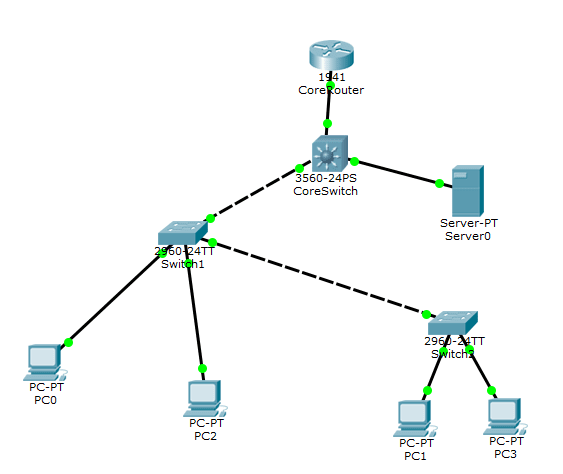
How it looks from a high level view:
The Cisco 3560 core switch below has the SVIs configured for routing the VLAN traffic. The two other 2960 switches are the Access switches that have clients uplinked to the various VLANs. Both clients at each switch are able to pull DHCP addresses from Server-PT on VLAN1 due to the ip helper address setup on each VLAN interface of the 3560 core switch.
Final Thoughts
Setting up inter vlan routing with multiple switches is straight forward and can definitely speed up your network as opposed to using the “router on a stick” method. Let me know in the comments below if you have any other questions concerning setting this up or alternative configurations you have found useful in your environments.