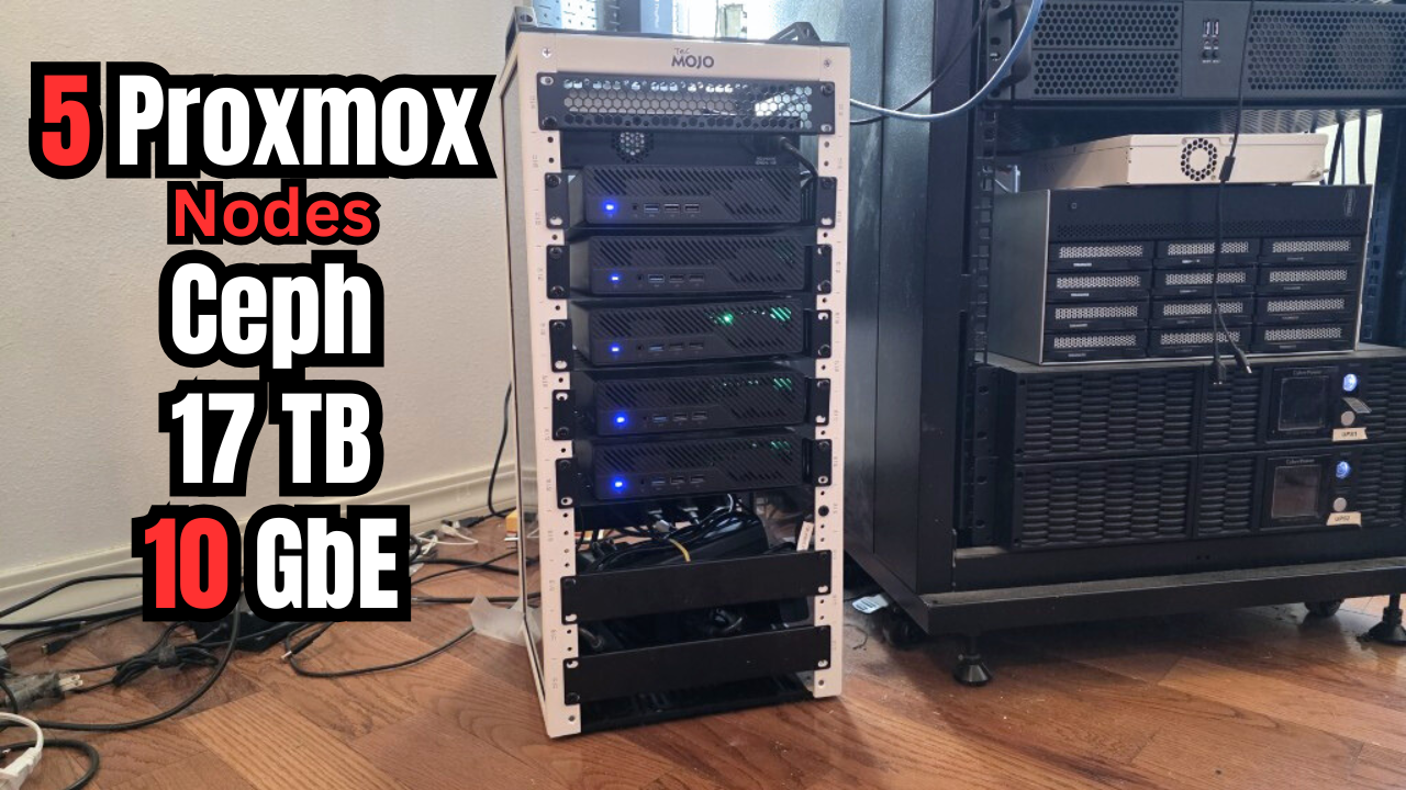
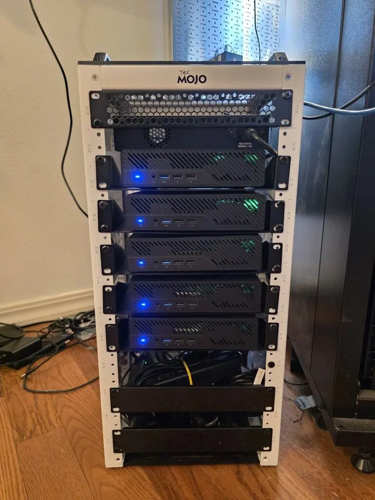
Over the last few weeks I have been deeply involved in a Proxmox home lab project that is designed to reshape my home lab as I know it as I am fully lifting my footprint from having any VMware at all running my production services. For this, I have chosen a lot of things that will be different for me historically compared to my full sized racks and VMware running things. I have chosen a 5 node Proxmox cluster running on top of Minisforum MS-01s which fit perfectly in my TecMojo 12-U mini rack. However, this has been quite a deep dive for me and more serious learning around Ceph, Proxmox networking, and NVMe OSDs. So sit back and enjoy this post as it is meant to be a walkthrough of my latest rendition of the mini rack as it has evolved even from what it was just a few weeks back
What I have been up to with the home lab
My home lab in 2026 has intentionally become smaller, not necessarily in compute or storage power but in terms of actual footprint. I am going away from my extensive full-size rack gear and collapsing things down to a mini rack this go around.
This is due to a lot of things, including industry trends, physical space, noise, power draw, and other things. This has coincided with my move to get totally away from VMware vSphere running my production workloads. Proxmox has become my defacto choice for this migration for many reasons.
First of all, refreshingly compared to VMware and Broadcom shenanigans, it is free and open-source. I no longer have to rely on paying for a VMUG subscription, which now no longer gets you licensing any way. I also wanted to give Ceph a real go in the home lab.
Honestly I really liked vSAN once I started using it in the VMware-based lab a few years ago and have been itching to get back to HCI for home lab workloads. But Broadcom killed vSAN in my opinion with licensing and I seriously saw many businesses walk away from vSAN back to traditional storage just simply due to the licensing changes. Ceph gives us a real way forward for HCI that is powerful and very enterprise ready. Ceph can scale as large as you want it to and is natively integrated with Proxmox.
Why I rebuilt my cluster using uniform nodes
I had played around with Ceph before and even use Microceph with my Docker Swarm cluster, but I always had the itch to do Ceph erasure coding. To do erasure coding, I went with a 5 node Ceph cluster. However, starting out with this, if you read my previous post here, you know I had dissimilar hardware and other variables. While it worked shockingly well, I was mainly limited by 2.5 GB networking. I wanted to get back to 10 GbE which is where HCI in general and Ceph in particular really start performing.
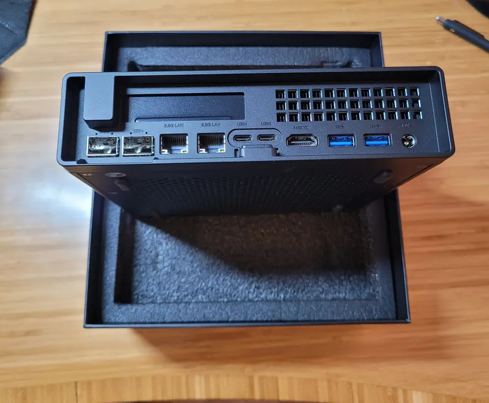
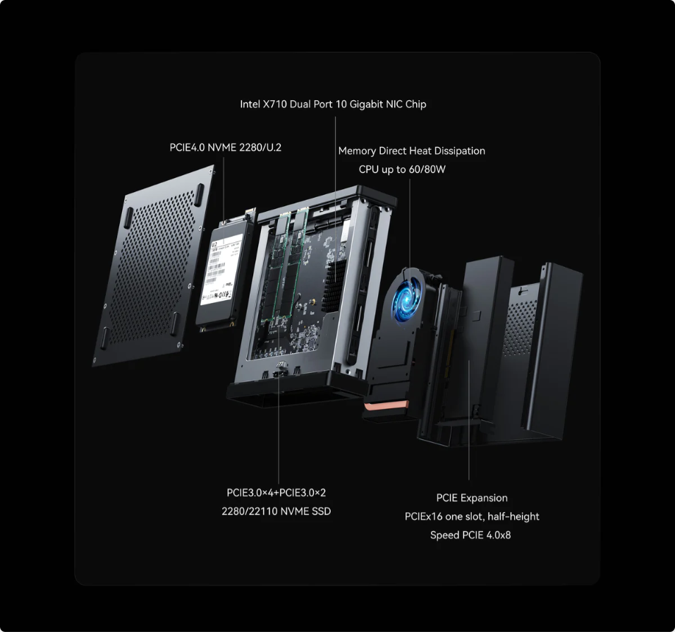
To do that, I decided to retrofit my original 5-node Ceph cluster that used dissimilar hardware with a 5-node uniform cluster made up of Minisforum MS-01’s. These are still great little machines and have native 2.5 and 10 gig networking built in, with (2) SFP+ connections. I already had (2) MS-01s that I had previously been using to run my VMware ESXi cluster connected to an all flash NVMe Terramaster NAS.
Read my review of the MS-01 here: Minisforum MS-01 Review: Best Home Server Mini PC Early 2024.
What I decided to do was buy (3) more MS-01 barebones units and use the memory and storage from my other mini PCs that would be replaced. This resulted in a uniform 5 node Ceph cluster running 10 GbE with erasure coding. Awesome!
So the reasons come down to the following for using uniform nodes:
- 10 gig networking for ALL the nodes in the Ceph cluster
- Uniform performance from all nodes
- No inconsistencies for HCI that would require troubleshooting and chasing different hardware
Ceph is extremely forgiving, but HCI in general does MUCH better on uniform hardware with the fewest amount of variables. Same machines, same networking, same storage, etc.
Storage configuration of the MS-01s with Ceph
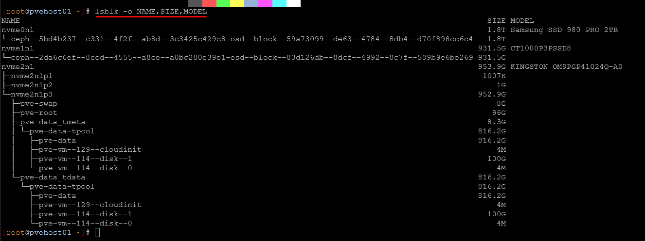
Currently with the MS-01s, I am running the following disks in the (3) NVMe slots of the MS-01. The M.2 slot that is closest to the U.2 switch is a PCI-e 4×4 and is the fastest slot in the MS-01. So, I have a 2 TB Samsung 980 2TB NVMe drive in each of the 5 MS-01 nodes in the cluster in this slot as the first OSD for Ceph. Then, in the next slot, you have a PCI-e 3.0×4 slot that I have also used for Ceph. Two fo the nodes have a 2TB drive and 3 of the nodes have a 1 TB drive here. Then in the slot furthest away from the U.2 switch in the MS-01, I have the boot M.2 drive. This is the slowest slot in the MS-01 so reserving this for the Proxmox install itself. These are 1TB PCI-e 3.0 NVMe drives in each of my MS-01s.
Careful migration to get to this
You may be wondering how I did the migration from all dissimilar mini PCs to the 5 MS-01s. This happened very carefully and one mini PC at a time. Believe it or not, what I was able to do was simply pull the drives out of the other mini PCs and install into the new MS-01s and Proxmox just picked right up and figured itself out on the new hardware.
The only thing I had to do was reconfigure the networking on the MS-01s Proxmox installation once things booted since the NIC naming changed with the different hardware.
This was a quick edit of the network config file in Proxmox:
/etc/network/interfacesHere I just simply changed the network interfaces for the default Linux bridge to the names of the new adapters. Below is an example of one of my PVE host’s network configuration:
auto lo
iface lo inet loopback

iface enp2s0f0np0 inet manual
        mtu 9000

iface enp2s0f1np1 inet manual
        mtu 9000

iface wlo1 inet manual

auto bond0
iface bond0 inet manual
        bond-slaves enp2s0f0np0 enp2s0f1np1
        bond-miimon 100
        bond-mode 802.3ad
        bond-xmit-hash-policy layer2+3
        mtu 9000

auto vmbr0
iface vmbr0 inet static
        address 10.3.33.210/24
        gateway 10.3.33.1
        bridge-ports bond0
        bridge-stp off
        bridge-fd 0
        bridge-vlan-aware yes
        bridge-vids 2-4094
        mtu 9000

# VLAN 2 - Dedicated VM bridge (no VM tagging needed)
auto bond0.2
iface bond0.2 inet manual
        vlan-raw-device bond0
        mtu 9000

auto vmbr2
iface vmbr2 inet manual
        bridge-ports bond0.2
        bridge-stp off
        bridge-fd 0
        mtu 9000

# VLAN 10 - Dedicated VM bridge (no VM tagging needed)
auto bond0.10
iface bond0.10 inet manual
        vlan-raw-device bond0
        mtu 9000

auto vmbr10
iface vmbr10 inet manual
        bridge-ports bond0.10
        bridge-stp off
        bridge-fd 0
        mtu 9000

# VLAN 149 - Dedicated VM bridge (no VM tagging needed)
auto bond0.149
iface bond0.149 inet manual
        vlan-raw-device bond0
        mtu 9000

auto vmbr149
iface vmbr149 inet manual
        bridge-ports bond0.149
        bridge-stp off
        bridge-fd 0
        mtu 9000

# VLAN 222 - Dedicated VM bridge (no VM tagging needed)
auto bond0.222
iface bond0.222 inet manual
        vlan-raw-device bond0
        mtu 9000

auto vmbr222
iface vmbr222 inet manual
        bridge-ports bond0.222
        bridge-stp off
        bridge-fd 0
        mtu 9000

auto vmbr0.334
iface vmbr0.334 inet static
        address 10.3.34.210/24
        mtu 9000
#Ceph

auto vmbr0.335
iface vmbr0.335 inet static
        address 10.3.35.210/24
        mtu 9000
#Cluster

auto vmbr0.336
iface vmbr0.336 inet static
        address 10.3.36.210/24
        mtu 9000
#Migration

source /etc/network/interfaces.d/*
One of my mini PCs required more work which I documented in another blog post my journey getting from a SATA SSD over to an M.2 drive. I used Hiren’s Boot CD and Macrium Reflect to image the SATA SSD over to the M.2 drive. This worked flawlessly and had zero issues doing that.
The Ceph lessons that understanding that took the most time
Ceph was one of the areas for me where the real learning and experience of “doing” really paid off. Ceph is incredibly forgiving to be honest. It will absolutely run when you think it may not and it will try its best to get your data back if things come back up.
One of the things I learned with my setup is provisioning Ceph with erasure coding, but also about setting it up for autogrow placement groups. I configured it so that these autogrow on their own when more storage is added.
However, I also shot myself in the foot on one of my nodes and actually rebuilt and wiped the wrong drive! DOH! In looking at the output of lsblk I misread the NVMe drive and zapped the wrong NVMe identifier. But, all was not lost. I simply removed the OSD that I actually wiped from the Ceph config to be safe and then just brought it back in as a new OSD and let Ceph do what it does and copy and move data back. do yourself a favor and double/triple check to make sure you have the right drive before you wipe anything ever.
My erasure coding setup
So here are the details of my erasure coding Ceph configuration.
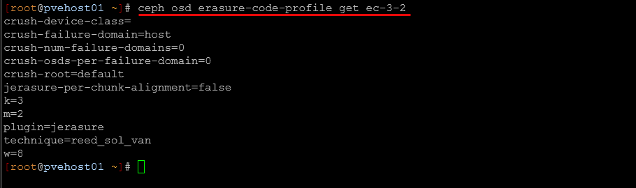
Erasure Coding Scheme: 3+2 and what this means.
- k=3 – Data is split into 3 data chunks
- m=2 – There are 2 parity/coding chunks
- Total: 5 chunks stored across your cluster
Storage Efficiency:
- My cluster can tolerate 2 simultaneous failures (any 2 hosts/OSDs)
- Storage overhead: 66.67% efficiency (uses 5 chunks to store 3 chunks worth of data)
- This is much better than 3x replication (33% efficiency)
What this configuration means in real-world terms:
- With 5 total chunks, you need at least 3 chunks available to read/write data
- Can lose any 2 hosts and still access your data
- Uses roughly 67% less storage than triple replication
- Great balance of efficiency and reliability for your setup
Networking took the most time in the cluster to get right
The main reason that I went with the MS-01s in the Ceph cluster was for 10 gig networking. Ceph really opens up in terms of performance when you have 10 gig in place. So, I had a plan of action in my cluster to get up to 10 gig and an order of operations.
- Replace the dissimilar mini PCs with MS-01s to get the 2 SFP+ ports in place
- Bought a 10 gig switch for the mini rack top of rack switch. You can read my review on that here:
- Migrate from the 2.5 gig ports on the MS-01s currently up to the 10 gig SFP+ ports
- Get a single 10 gig connection up and running with the MS-01s
- Get both SFP+ ports up and running with connectivity on the cluster with LACP in place
So, I wanted to take a guaged approach to introducing 10 gig connectivity in the cluster. Bonding them with LACP seemed to be the obvious choice to make the best use of both “lanes” of 10 gig connectivity to work together in a meaningful way. This was the plan, but I ran into some “pain” along the way, mostly due to some mistakes I made in implementing the config.
Jumbo frame issues
The first issue I had was self-inflicted jumbo frame issues. I missed the MTU config on a couple of my MS-01s Proxmox networking config and had a few hours of troubleshooting some really weird behavior because of this.
The dangerous thing with Jumbo frames is they don’t always give you an obvious issue that you can easily pinpoint. Instead, you may see some servies work just fine with a mismatched jumbo frame configuration but then see other apps and services have all kinds of issues. This is exactly what I saw.
Because:
- Small control packets work
- ARP works
- ICMP 1500 works
- SSH works
- Web UI works
But:
- Storage I/O stalls
- Ceph flaps
- VM migration fails
- SMB metadata errors
- Only large bursts fail
It is easy to forget, but you actually need to make sure you have jumbo frames enabled in the entire chain of communication:
VM → virtio → bridge → VLAN → NIC → Switch → NIC → bridge → VM. Even if one hop is 1500, large frames get dropped somewhere in that chain.
Linux bridge, VLAN tagging, and Firewall flag issues when used in combination
I learned something very interesting about Proxmox and Linux bridges in general that was discovered after I started trying to enable LACP across my cluster hosts. After enabling the first host with LACP, everything was working fine. But after enabling LACP on the second host, I started to see very weird issues in my cluster. I couldn’t ping certain hosts on the network, or certain hosts even on other segments started going down. Very strange.
When I first looked at this, it looked like “LACP was being flaky,” or I was having issues with my new switch. But, I discovered the issue was not LACP itself, but how Proxmox handles VLAN tagging when the VM firewall is enabled.
When you configure a VM NIC with:
- bridge=vmbr0
- tag=<VLAN_ID>
- and firewall=1
Proxmox dynamically creates additional bridge and VLAN subinterfaces behind the scenes. These are not defined in /etc/network/interfaces. They are generated at runtime to allow per-VM firewall filtering on tagged traffic.
For example, if a VM is configured with tag=149 and firewall enabled, Proxmox can create interfaces such as:
- vmbr0v149
- bond0.149
- nicX.149
- and related fwbr, fwpr, and tap devices
These interfaces can form separate VLAN processing paths specifically for firewall filtering of your VMs. Under a single physical NIC, this often works without obvious symptoms. However, once I configured an 802.3ad LACP bond, that is when I started to see problems. The dynamically created VLAN subinterfaces could exist on the bond and possibly on the bond slaves. This will cause multiple VLAN plumbing paths.
I don’t think this created a classic spanning tree loop, but it did create parallel forwarding paths that were not part of my intended traffic flow. So, it led to inconsistent pings, etc.
Ceph and CephFS
In this cluster, I am running both Ceph and CephFS. CephFS is a file system that exists on top of Ceph underneath. So you get the resiliency of Ceph storage that underpins normal file storage that you can use for all kinds of things.
One of the cool things that I do with CephFS is run shared storage for my Kubernetes cluster. With CephFS, you get easy to interact with storage that is also shared across your nodes. So you can work with the files with any tool that you want to use to connect to your CephFS Proxmox host and copy or migrate data you want to live in CephFS.
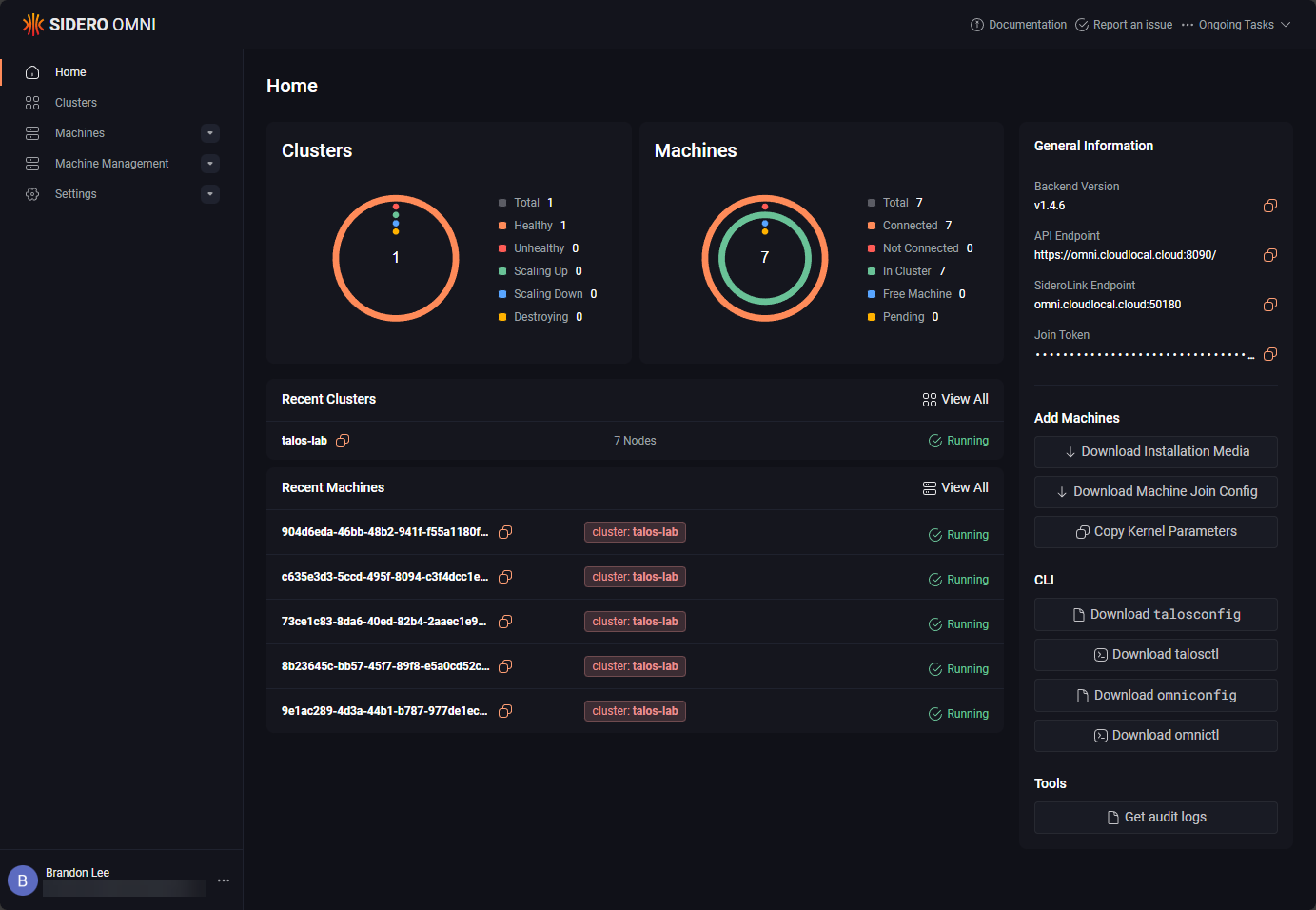
Running Talos Kubernetes on Top of CephFS
Once I got my networking lined out with the bridge, VM VLAN tagging, and firewall flag configuration, layering my Talos Kubernetes setup on top of that was pretty simple. In this configuration, I run Talos Linux as virtual machines stored directly on my Ceph RDB storage, and then I have a storage provider that I have configured to work to have CephFS as the shared persistent storage for my Kubernetes cluster.
Some people have asked me or I have seen some criticism on my posts about this as to why I would choose to run Talos in Proxmox instead of on baremetal, especially with Sidero Omni to manage Talos? Well, I can tell you this setup works beautifully and gives you a lot of advantages I think. First of all, when you run Talos on top of Proxmox, it abstracts the Talos nodes from the underlying physical hardware.
This means if you want to take down a physical node for maintenance, you can still have ALL of your Talos Kubernetes nodes up and running. Also, it allows me to use the cluster and the hardware for more than just Kubernetes. I can use Proxmox to run standalone Docker nodes, Windows nodes, or really anything else I want to do with the resources. And, for me, options are king in the home lab.
All in all, I think this is a great combination of hypervisor, Kubernetes management, and immutable Kubernetes nodes with Talos that make this a killer setup.
Why five nodes was the right number
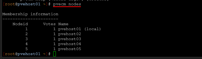
Could I have gotten away with three nodes? I could. That would have been the minimum. Four nodes would have added some margin in there as well. However, five nodes gives the cluster breathing room. With the 5 nodes, I can lose two nodes and still have quorum in the cluster. Ceph has more flexibility in data placement.
Also, maintenance windows are less stressful because taking a node offline doesn’t push the cluster near its limit or failure tolerance threshold.
Seventeen terabytes in a mini rack
While 17 terabytes might not sound massive compared to enterprise storage arrays, for me, it is pretty awesome to have an all NVMe distributed storage solution across five physical nodes and the cluster support VM migrations, Kubernetes workloads, and tolerate node failures like a boss.
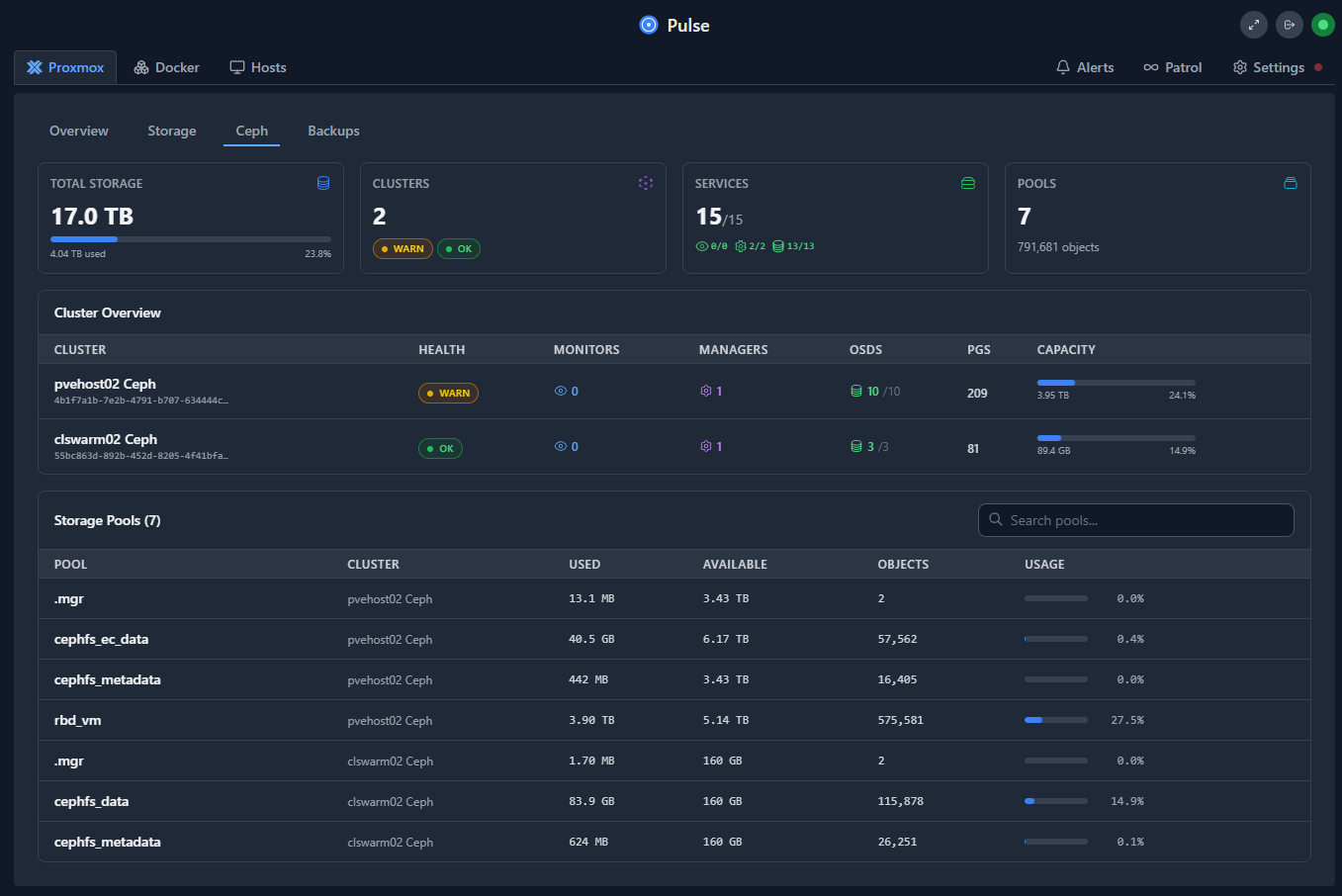
And, what is even more cool is that all of this lives inside a compact mini rack footprint that is powered by small mini PCs. Having a setup like this no longer requires having enterprise server gear with all the power draw they require and it fits into a MUCH smaller footprint and is much quieter.
Performance Testing!
Ok so I know everyone would be curious on the performance of this little mini cluster. All benchmarks were captured while approximately 22 virtual machines were actively running on the cluster. So, to say this is real world, is definitely true. They reflect real-world contention and distributed storage behavior.
The rbd_vm pool is replicated (size 2, min_size 1). The cephfs_ec_data pool uses 3+2 erasure coding. VM disks live on the replicated pool. CephFS data lives on the erasure coded pool.
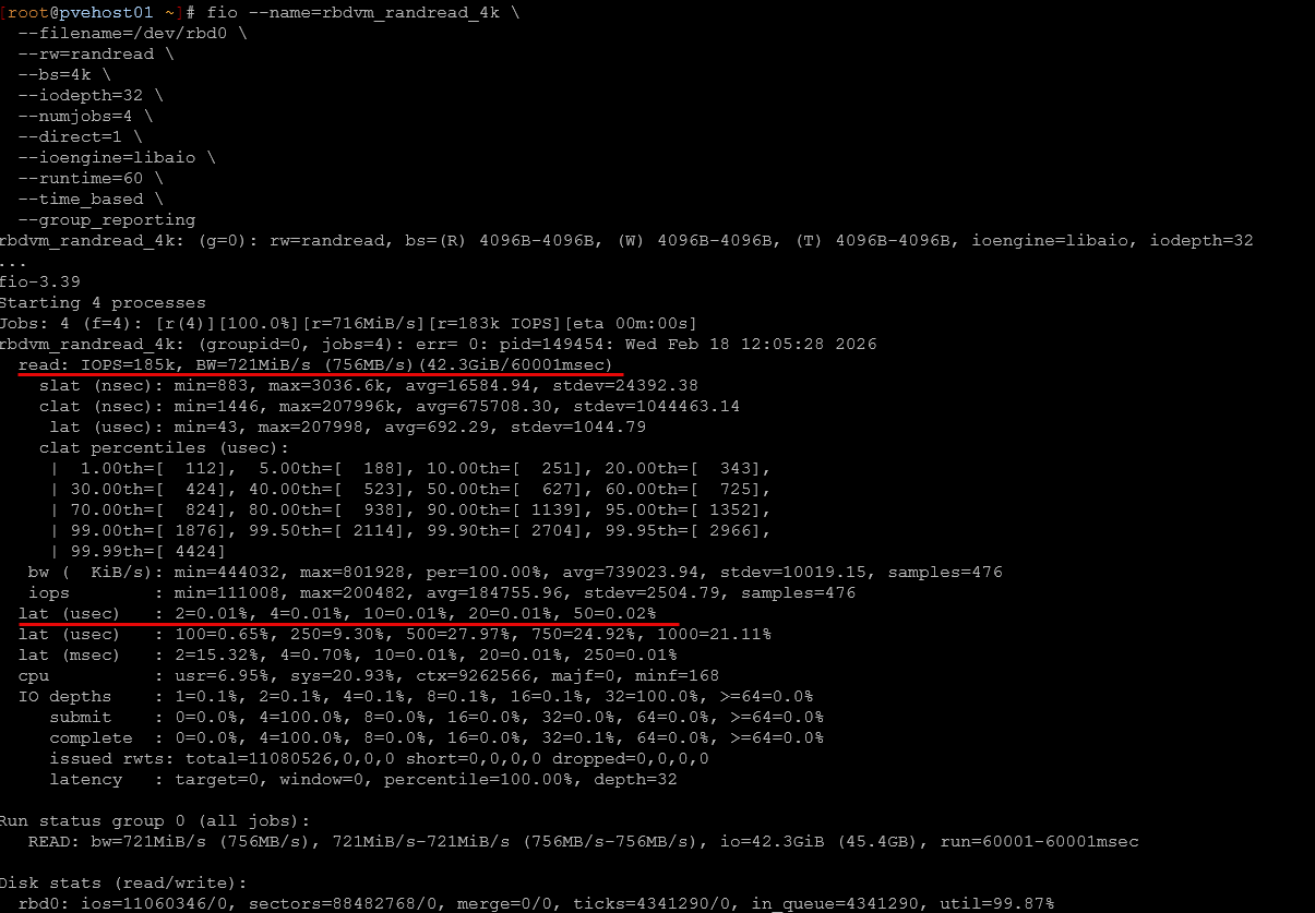
Block-level tests were performed using fio against a mapped RBD image. Object-level tests were performed using rados bench with 4 MB object sizes.
RBD Performance (Virtual Machine Pool – Replicated, size 2)
4K Random Read (QD32, 4 jobs, 60 seconds)
- ~185,000 IOPS
- ~721 MiB/sec sustained throughput
- ~0.69 ms average latency
- ~1.8 ms 99th percentile latency
These numbers I thoguht are excellent small-block read performance for distributed storage over 10Gb networking. It has sub-millisecond average latency. This helps to confirm the cluster is balanced and not bottlenecked at the OSD or network layer. Reads scale efficiently because they can be served in parallel across nodes. So, blazing performance here.
4K Random Write (QD32, 4 jobs, 60 seconds)
- ~7,700 IOPS
- ~30 MiB/sec throughput
- ~16–18 ms average latency
- ~30 ms 99th percentile latency
This is where you see the most demanding workload for distributed storage in random writes. Each write must be replicated and committed before acknowledgment. With replication size 2 and live VM load in the cluster with 22 VMs running, this latency profile is very good. The important thing I observed is stability. There were no latency collapses or cluster health issues during the load test.
4K Mixed 70/30 Read/Write (QD32, 4 jobs, 90 seconds)
- ~15.9K read IOPS
- ~6.8K write IOPS
- ~0.45 ms average read latency
- ~17.7 ms average write latency
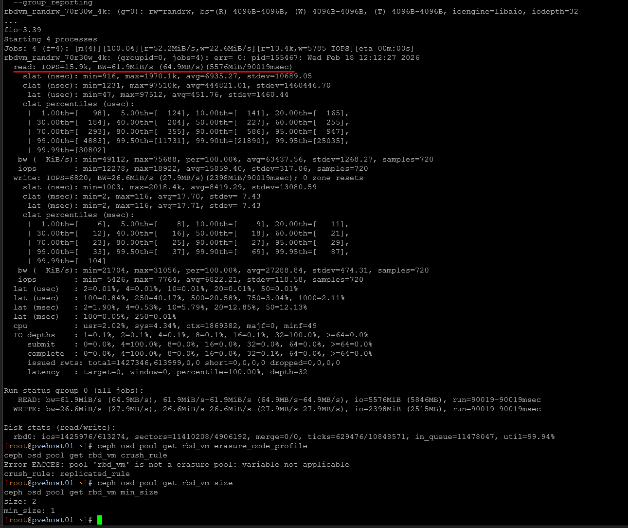
This mixed workload more closely resembles what you would see in a cluster like this. Reads are still very responsive, while writes carry the replication overhead that we expect. Latency was steady, even with active VMs on the cluster.
1M Sequential Write (QD16, 60 seconds)
- ~542 MiB/sec sustained throughput
Sequential IO benefits from the the parallel operations across OSDs and network links. Sustaining over 500 MiB/sec of replicated write traffic on a live cluster like this I think is great. It demonstrates that the architecture can push high throughput without becoming unstable. Also, the large block throughput is getting to the practical limits of 10Gb networking.
Raw Ceph object performance (rados bench)
To validate performance at the object layer independently of RBD and Proxmox, I ran rados bench using 4 MB object sizes.
4 MB Object Write (60 seconds)
- ~786 MB/sec sustained throughput
- Peak bandwidth over 1.1 GB/sec
- ~81 ms average latency per 4 MB object
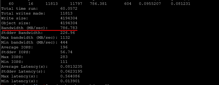
You might think the 81 ms latency is sluggish and slow. However this is measured per 4 MB transfer, not per 4K IO. Large IO operations will take longer in a distributed system due to replication and network transport. The key metric here is sustained throughput. This approaches line-rate on a single 10Gb link and definitely confirms to us that aggregate bandwidth across the bonded 10Gb interfaces is being effectively utilized.
4 MB Object Read
- ~1.23 GB/sec sustained throughput
- ~51 ms average latency per 4 MB object
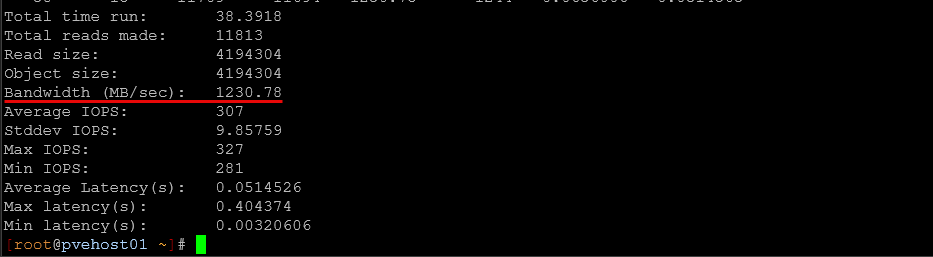
Because the cluster uses dual 10Gb links bonded with LACP and distributes reads across multiple OSDs, aggregate bandwidth can exceed single-link limits. This confirms that both the networking and OSD layer are scaling properly across all the nodes.
Happy with the results
I am really happy with the performance here. A few important points help put these numbers in context:
- The VM pool (rbd_vm) is replicated, not erasure coded. Erasure coding is used only for CephFS data
- Small 4K random writes are latency-bound due to replication and durability guarantees with Ceph
- Large sequential IO show the true throughput capability of the cluster
- Object-level tests also confirm that the underlying Ceph OSD and network layers are performing near expected limits
- All benchmarks were captured under active workload, not on an idle system
The takeaway is this little mini rack Proxmox Ceph cluster is delivering strong read performance and predictable write behavior. It also is capable of high sequential throughput on dual 10Gb networking.
Video
Wrapping up
I am really excited to see what I can accomplish with my new mini rack Proxmox-powered home lab that is running Ceph and CephFS, along with Talos Kubernetes. It can run basically anything I want to run at this point and I am really looking forward to the workloads and experimentation I can do in the lab in 2026. What do you guys think? Would you change anything that I have done here? I would like your honest feedback.
Google is updating how articles are shown. Don’t miss our leading home lab and tech content, written by humans, by setting Virtualization Howto as a preferred source.
About The Author


So cool Brandon, you went all out! I am looking at building a mini rack this year at some point.
I’d did not see any performance numbers agasint the pool. Erasure coding probably made those nvmes(consumer? no plp? no dram cache?) slow as floppies in your pool. please provide your #s:
rados bench -p 19 write –no-cleanup && rados bench -p 19 seq && rados cleanup -p
b101,
Thank you for the nudge on the performance numbers! I just hadn’t had time as of yet to do the benchmarking I wanted to do. I have now updated the post with all the numbers so you can see. Just to clarify, my VM pool is replicated with 2 replicas. CephFS is erasure coded with 3+2 EC for CephFS. Also, these results were captured with 22 VMs powered on and running so definitely not a “quiet” cluster by any means.
RBD (replicated pool)
4K random read: ~185K IOPS, ~0.7 ms avg latency
4K random write: ~7.7K IOPS, ~16–18 ms avg latency
1M sequential write: ~542 MiB/sec sustained
rados bench (4 MB objects)
Write: ~786 MB/sec sustained
Read: ~1.23 GB/sec sustained
The 4 MB latencies (51–81 ms) are per large object transfer, not 4K IO. Throughput is near practical limits of dual 10Gb networking, which validates the OSD and network layers are healthy.
Cheers,
3+2 erasure coding actually means 3/5=60% efficiency. 😂
Do you know, how this setup handles losing one node and two individual disks in different nodes? Would 6+4 erasure coding make a difference in this case?
BR
Felix
Fexlix,
Good catch on the math! Yes, 3+2 is 60% usable efficiency. 😂
In my case, the 3+2 EC profile is used for the CephFS data pool with failure domain set to host. So chunks are distributed across different nodes. That means the pool can tolerate up to two failures, as long as they don’t violate the CRUSH placement rules.
Losing one full node is fine. Losing two OSDs on different nodes is also fine. The risk would be losing three chunks that belong to the same placement group.
As for 6+4 profile, that would require at least 10 OSDs in the failure domain and would increase CPU and network overhead. On a 5-node cluster, 3+2 is basically the practical maximum stripe width. Moving to 6+4 would only make sense in a larger cluster where you want higher durability and are willing to accept the additional overhead.
For this size lab, 3+2 gives a reasonable balance between efficiency and fault tolerance.
And the total power draw is?
Gai,
Around 200 watts under normal workloads.
Brandon